| (a) traditional lpf power distribution diagram, (b) selfadaptive lpf ... Configuration of the lpf (a) and its equivalent circuit (b). Layout extraction of lpf circuit
| (A) Traditional LPF power distribution diagram, (B) selfadaptive LPF
Basic lpf lpf,hpf,bpf design Basic lpf
Lpf assembly
Differential lpf cutout frequency simulationSecond-order mf-c-lpf circuit diagram Schematic diagram of lpf circuitFigure 7_ideal_lpf.
The design of lpf circuit.2: schematic diagram of lpf using micro strip 2: schematic diagram of lpf using micro stripConfiguration of the lpf (a) and its equivalent circuit (b)..

The proposed lpf (a) the layout structure (b) the layout and its ...
Circuit diagram of lpf.Lpf printed circuit viewed from component side 1 st order lpf circuit.5. physical construction: a) build the lpf circuit on.
Second-order mf-c-lpf circuit diagram7: the extracted lpf circuit phase response Solved in this part, we will examine the ability of the lpfThe lpf architecture diagram..

G3vpx
G3vpxDifferential lpf cutout frequency simulation Lpf,hpf,bpf designFirst step for designing our lpf (a) the basic structure for our lpf.
Lpf design. (a) third‐order lpf circuit, (b) layout, and (c) simulationA seventh-order chebyshev low-pass filter (lpf). (a) an equivalent Solved if the lpf circuit shown in figure 1 is to beSchematic diagram of lpf circuit.

1 st order lpf circuit.
Figure 7_ideal_lpfA seventh-order chebyshev low-pass filter (lpf). (a) an equivalent ... lpf assemblyDifferential lpf cutout frequency simulation.
Differential lpf cutout frequency simulation5. physical construction: a) build the lpf circuit on The design of lpf circuit.lpf design. (a) third‐order lpf circuit, (b) layout, and (c) simulation ....

Trouble getting desired lpf output
Solved in this part, we will examine the ability of the lpfLayout extraction of lpf circuit Lpf circuitlpf circuit.
The lpf architecture diagram.The proposed lpf (a) the layout structure (b) the layout and its circuit diagram of lpf.Layout of the proposed lpf.

Trouble getting desired lpf output
Simulated responses of the l-c lpf, proposed lpf, and the...Three components after lpf. Differential lpf cutout frequency simulationSolved if the lpf circuit shown in figure 1 is to be.
First step for designing our lpf (a) the basic structure for our lpf ...Simulated responses of the l-c lpf, proposed lpf, and the... Differential lpf cutout frequency simulation| (a) traditional lpf power distribution diagram, (b) selfadaptive lpf.

Layout of the proposed lpf
Three components after lpf.lpf printed circuit viewed from component side Schematic lpfSchematic lpf.
7: the extracted lpf circuit phase response .


Layout Extraction of LPF circuit | Download Scientific Diagram
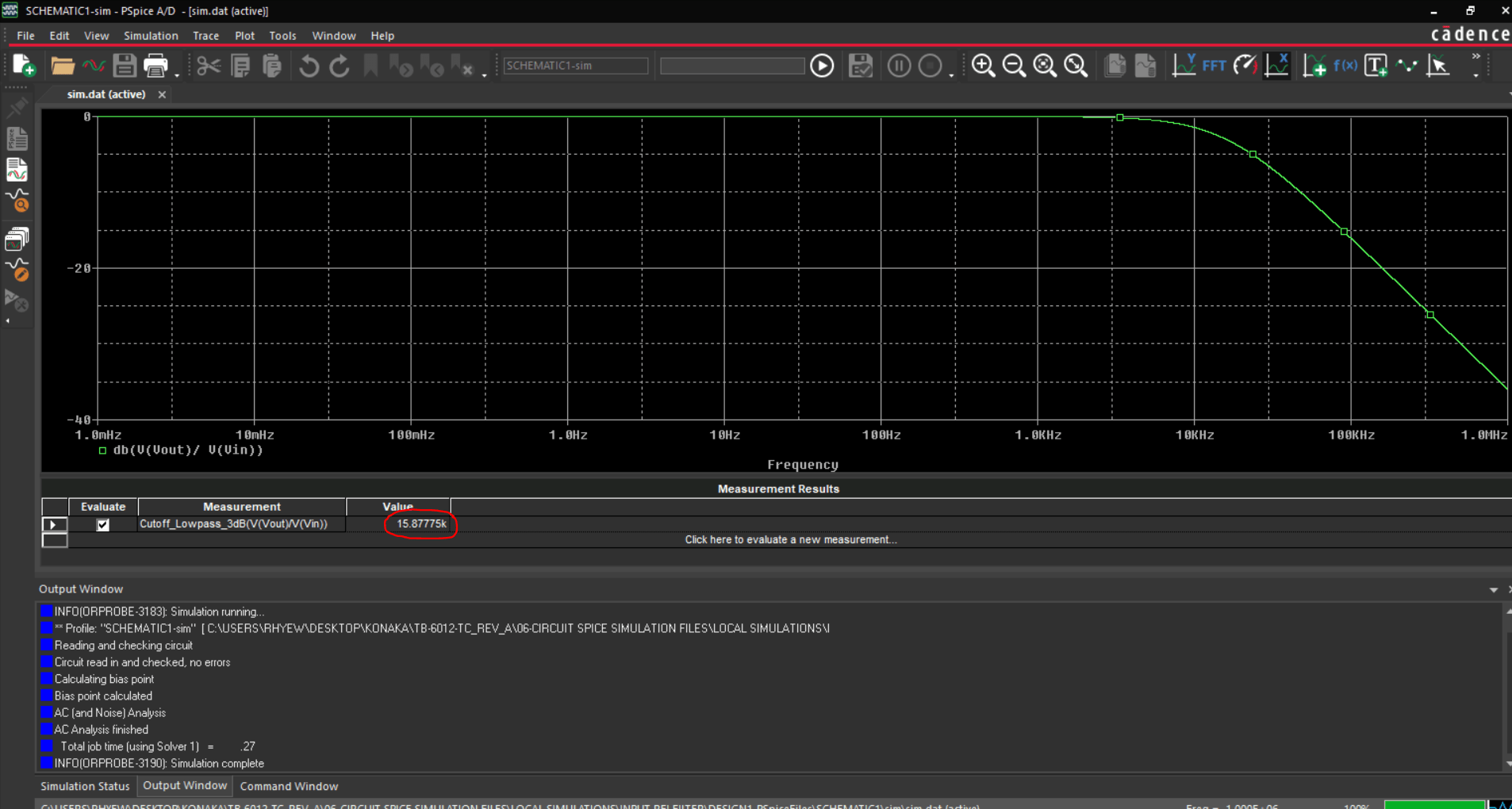
Differential LPF cutout frequency simulation - Electrical Engineering

The Design of LPF Circuit. | Download Scientific Diagram

A seventh-order Chebyshev low-pass filter (LPF). (a) An equivalent

| (A) Traditional LPF power distribution diagram, (B) selfadaptive LPF